Building a Split Keyboard part 2
In part 1 I covered the physical/mechanical design of my keyboard project. In this post we’ll dive into the electrical design and touch on firmware development.
Handwiring
Very early in my research I decided that I wanted to pursue a hand wired build. This decision was made for a few different reasons.
- Less to learn – With a hand wired build I wouldn’t have to learn PCB design, nor would I have to get up level my soldering skills to work with SMD components.
- Easier to debug and repair – Hand wiring would allow me to debug problems, and fix design mistakes with a multi-meter and basic soldering. Printed circuit boards are far more final and the iteration time on mistakes is higher and more expensive.
Parts overview
Keyboards are made a handful of parts.
- Switches – These get pressed closed and connect circuits that the microcontroller can read.
- Diodes – These help control the flow of current and prevent the matrix from ‘ghosting’. Ghosting is a pretty involved topic and I recommend this guide if you want to learn more about why you need diodes in a keyboard. Thankfully there are no choices here and you can just buy 1N4148 diodes.
- Microcontroller – This is the brains of the keyboard and where firmware is uploaded.
- Interconnects – There are a few different ways to connect the halves of a split keyboard with a variety of trade offs.
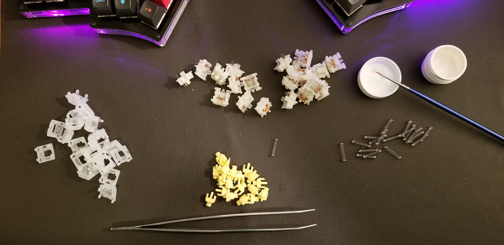
Switches
There are a dizzying number of choices for switches with prices ranging from $0.30 / switch to $2 / switch. What you choose is mostly preference. I used my previous experience with other boards and lots of Youtube reviews to make my decision. I chose to go with Gateron Yellows. They are a cost effective linear switch that has many good reviews. I chose to lube them with Crytox 205g0, and will continue to lube switches in the future. Lubing makes a huge improvement to how smooth switches are and improves the sound of switches. Lubing is a labour intensive process and it took me approximately one hour for each 10 switches. I followed this guide when for my lubing process and it was great.
Microcontrollers and IO Expander
Microcontrollers are the brains of the keyboard. The microcontroller polls the column pins on the matrix and reads which switches are connected by reading signals on the row pins. There are a ton of potential microcontroller options with different number of pins, features and price points. I chose to go with a MicroPro clone as many of the build guides I read had used them and there is excellent support for ATMega chips in QMK. Many split keyboard builds put a microcontroller in each half. This makes the firmware simpler to write as you can flash the same firmware to both sides and QMK configuration can take care of figuring out which hand is primary, and setting up the I2C bridge.
I didn’t want to put a microcontroller in each side as I thought it was wasteful, and I didn’t want to have flash both sides of the keyboard when I have to change the firmware. Instead I chose to use an IO expander, specifically the MCP23017 I originally goofed and bought the MCP23S17. Which was totally wrong, as the S version uses a serial connection (bad), while the 0 version uses I2C (good). Using an IO expander makes the firmware more complex as the code to drive the I2C is not provided by QMK, and needs to be custom. The Ferris and Ergodone projects provided a great reference for my firmware, and IO expander wiring.
Interconnects
Next on the decision list was interconnects. In a split keyboard you need a way to join the two halves together. There are a variety of options to do this. The options range from using a ribbon cable, to RJ45, USB-C, and TRRS. I’m not a fan of TRRS as it creates the possibility of shorting out the secondary side if the cable is plugged in while the keyboard is on. I had initially planned to use an RJ45 cable and even bought parts and a nice cable. However, when I started iterating on the case designs the RJ45 connector was really large, and hard to mount on the case. Because of the size, I ended up going with USB-C ports. There are easy to find USB-C breakout boards that have mounting holes and USB-C cables are easy to find or make.
Electrical Prototype
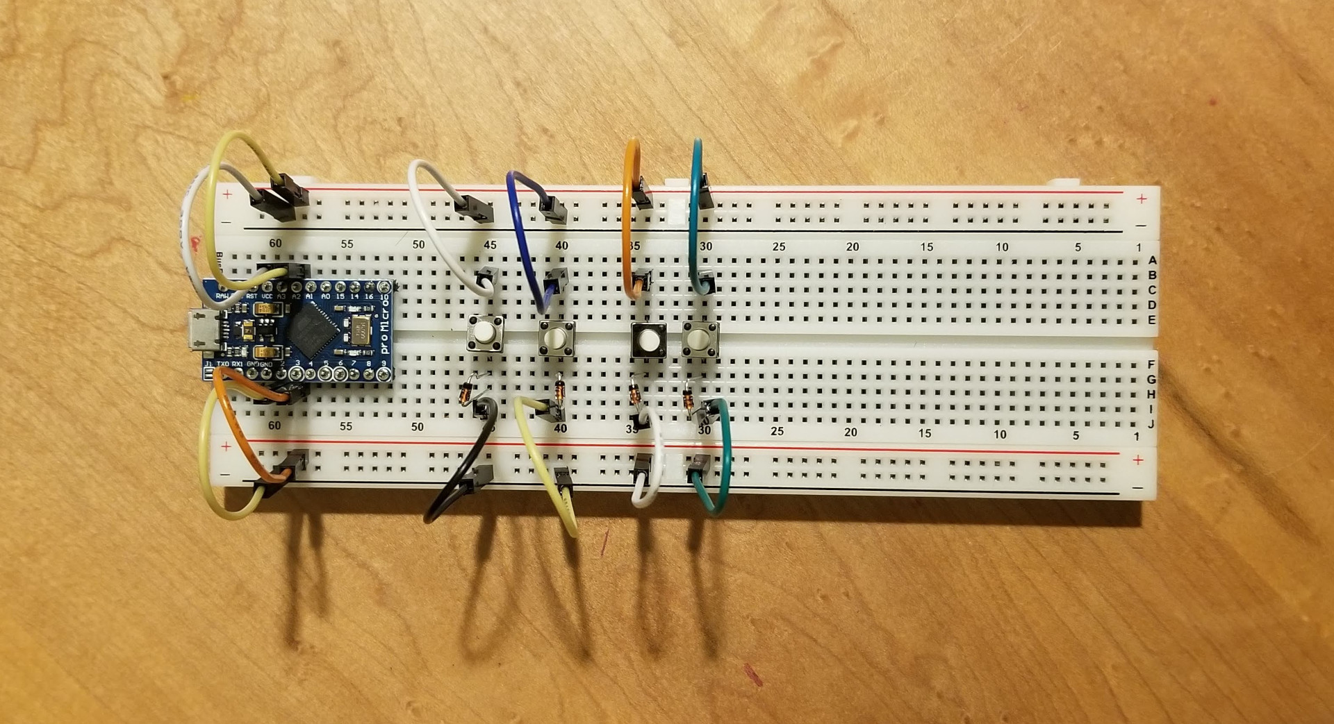
After buying the first wave of parts I wanted to get a proof of concept for the firmware and test out the wiring plan before doing any soldering. I decided to build a prototype on a breadboard with only four keys. This helped me understand how a matrix, the IO expander, and firmware worked:
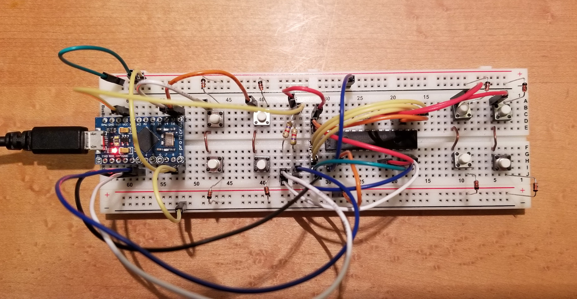
Once I got the first four switches working, I added in the IO expander and a second set of four keys attached to it. This let me debug the firmware and build more confidence that I could actually execute the build I was planning:
Firmware
In tandem with the breadboard prototypes I developed rudimentary firmware. This was helpful as the firmware for the IO expander was a bit of an unknown to me. Thankfully, the Ferris keyboard uses the same IO expander as me. I was able to copy/paste most of the I2C code for the prototype. I’m hoping that will continue working in the final board. I have the firmware I wrote up on GitHub
I ran into some trouble getting the I2C bridge working. I initially forgot to wire voltage into the I2C bus which made for fun debugging session. Once I had current applied to the bus with the correct resistors, results were much better. While the keyboard was ‘broken’ I used hid_listen to capture the debug print statements that were in the firmware.
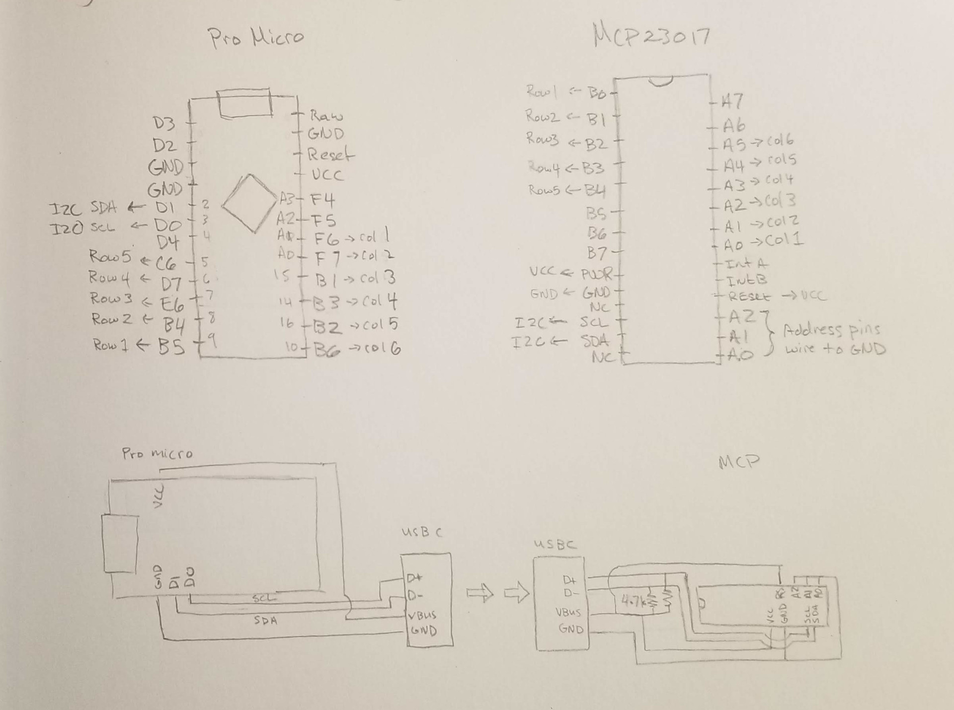
With a working prototype that included two halves, I sketched out wiring diagrams for the final build:
That’s it for now, I’ll have another article up covering the assembly, and final firmware development as I get it complete.
There are no comments, be the first!