Designing my first Keyboard PCB
In 2021, I designed and built a custom split keyboard . I quite enjoy that keyboard, and it has been my daily driver for the past eight months. After completing the hand wired board, I wanted to learn more about electronics, and keyboards. The natural next step to me was to learn how to take my custom layout to the next level of completion. I figured designing a printed circuit board and building it was a pretty formidable challenge. Another goal for this project would be to attempt per-key RGB, which turned out and additional layer of heat.
Learning KiCad
Like many hobbyists, I chose to use KiCad to do my design. KiCad has everything you need to do hobby sized projects and the community support history is quite helpful. I started off doing the software introductory tutorials, and then reading some great tutorials that others have published . These tutorials helped me get more comfortable with KiCad, and find good libraries. In my design I used the following KiCad libraries:
- https://github.com/pierrechevalier83/keyboard_footprints/ – has choc and mx footprints.
- https://github.com/tmk/keyboard_parts.pretty – has a variety of switches holes and other components.
- https://github.com/keebio/Keebio-Parts.pretty – Library from keeb.io with switch and USB port footprints.
I started off using an outline I had drawn in inkscape with key switch with a ‘base’ board that is just a keyboard with no frills. Once I had that looking good, I wanted to do something a bit harder. The next natural step was to add RGB! Because I was using an IO Expander I wouldn’t be able to use ‘smart’ LEDs like WS2812 compatible ones. Instead I would have to use a discrete LED driver. After reading up on what QMK supports, the best option for my design was the IS31FL3731. This driver had ample space for the 81 (27 * RGB) LEDs on each side. I would need to put one driver on each side as the USB-C interconnect cable has no room. These LED drivers are controlled by an I2C bus.
Components
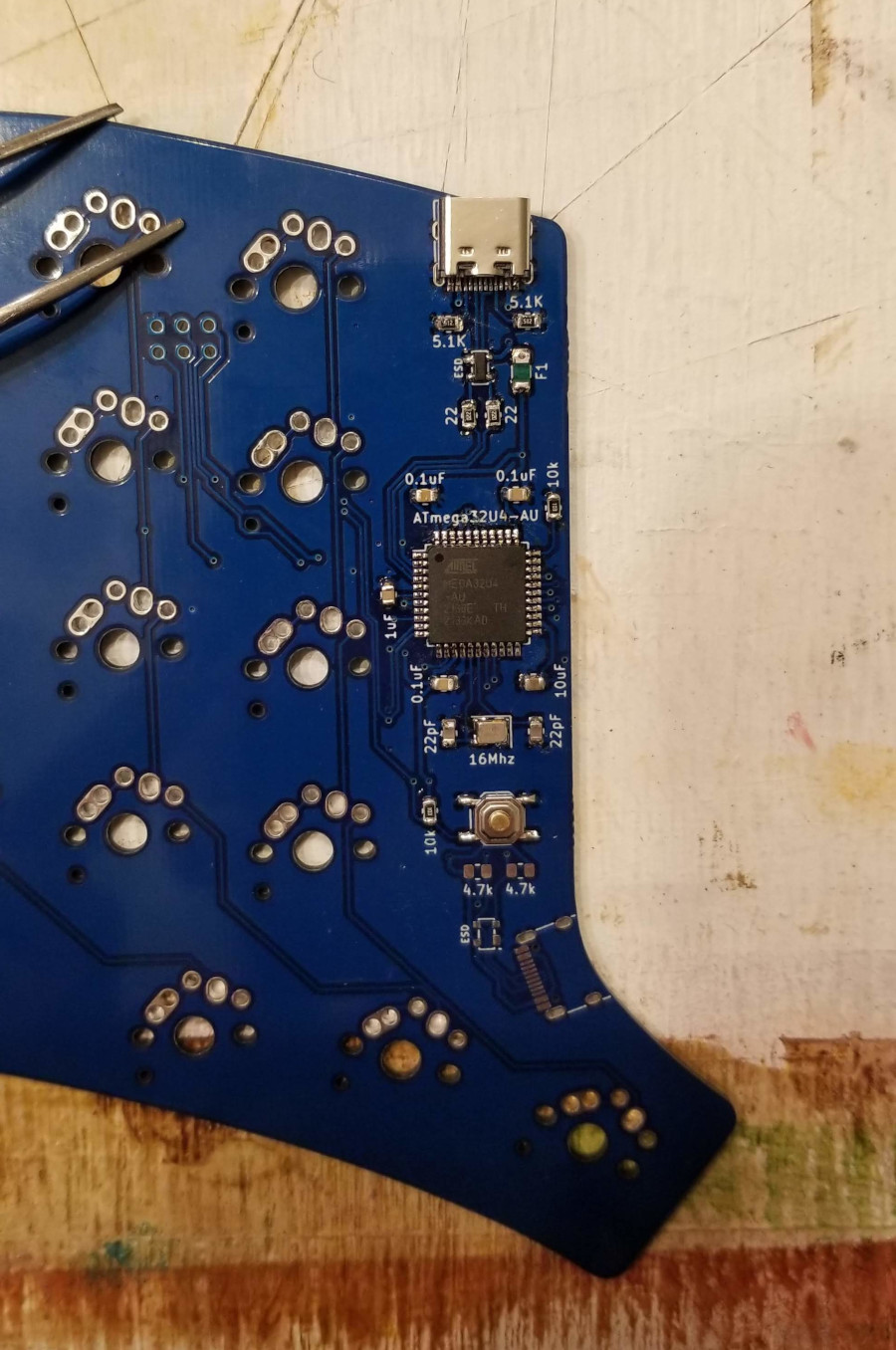
I figured that designing the board and figuring out how to build and RGB matrix would be enough ‘new stuff’ that I should re-use what I could from the previous build. Once again, I used ATMega32u4 controller and MCP23017 IO-expander. These components worked well on the hand wired build, and schematics for ATMega32u4 based boards are widely available. I also chose to have two separate halves as doing a single reversible board with the components I had chosen wouldn’t be feasible. As an additional benefit, doing two different halves would let me do a fancy silkscreen on the back. The design process for the back silk screen easily added two weeks to the board design time, but I think it was worth the investment.

After I had the first draft of the board designed, I decided I wanted to try a low-profile build. This meant updating switch footprints to be compatible with choc switches. Another round of revisions later, and I was ready to get boards printed. I went with JCLPCB as I was trying to keep my budget low and didn’t need the higher-end product that North American suppliers provide. I picked up most of the components from LCSC and the rest from digikey. I had a really hard time sourcing controllers, LED drivers and had to order them separately. I ended up paying more for shipping than I wanted to, but that’s life in hobby electronics.
Firmware
Getting the firmware updated for the new board design was pretty straight forward. The bulk of the work was updating pin assignments. Adding the LED matrix configuration took more work as I got the spacing and alignment with the keys wrong. Getting the matrices align took additional trial and error. Because the RGB configuration could only be tested once the board was assembled it happened at the very end, after debugging the numerous hardware bugs.
Hardware Bugs
While most of the keyboard design worked on the first time, it wasn’t entirely smooth sailing. After the initial assembly, I attempted to power on just the left side as it has the USB host connection. While the keyboard part worked, the LEDs wouldn’t power on. I tried poking around with a multi-meter and blew the fuse? At first, I thought I bricked the board but after testing with a multi-meter I found that the fuse had 4 Million Ohm resistance. I thought I had purchased poly fuses, alas I did not. I had to order poly fuses as replacing SMT components with a pencil iron is unpleasant.
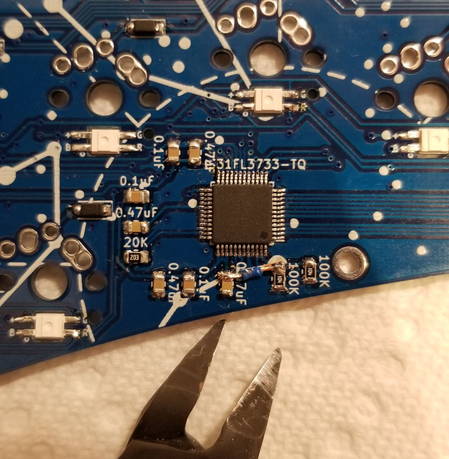
With proper poly fuses, and some help from the folks on the QMK discord, I was able to debug the LED driver problem. I had forgotten to apply 5V to the SBD line. When this pin is low, it tells the LED driver to power down, which is why the lights didn’t work. I bodged this with some wire and got the lights on!
I finally had the left side lights working. However, when plugging in the right side the board would instantly short out. I was quite puzzled and reviewed the schematics and board layout a few times before. I started to use a multi-meter to double check continuity between the USB port and the IO expander. I eventually figured out that I had the ESD device wired backwards which of course was the source of the short. Fixing the short was simple, as I was able to pop the device off.
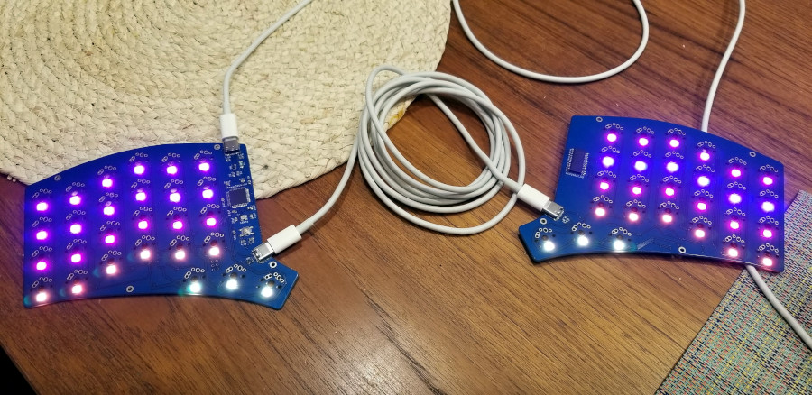
With those problems take care of, I was now faced with an off colour row, an one off colour LED on the left side and the incorrect LED layout. As mentioned before the layout problem was caused by me including holes in the LED matrix because I thought it had to be a rectangular grid, which wasn’t true. With the layout issues solved, I still had some off colour LEDs. Once again double checking the schematics and board layout for issues. With some more help from the QMK discord community I was tried reflowing the joint on the effected LEDs. Re-flowing joints fixed the one always red LED, but not the strand of blue cast LEDs. Next, I tried re-flowing the pins on the LED driver and got the problem fixed. Clearly there was a minor bridge somewhere.
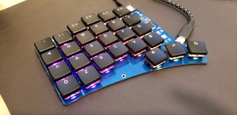
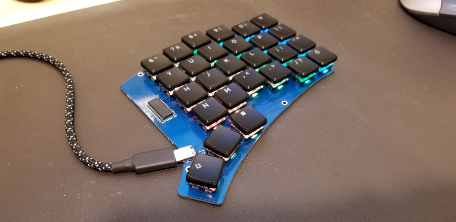
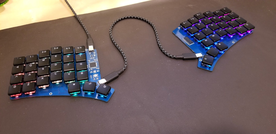
As mentioned before I went with a low profile case-less design on this build. I used choc reds lubed with Krytox205g0. The caps are MBK glow, and cables are re-used from my previous build.
Show me the source!
Why thanks for asking. I’ve published the schematics for the hardware and the firmware on GitHub.
What’s next?
This project was really challenging. I broke a few things along the way including bricking a board and tearing the pads off a few more. But I also learned tons and am quite happy with how the result came out. My next keyboard project will likely to design a version of the RGB board that has bottom mounted ports so it is compatible with both a switch-plate and case. I’ll also take care to design all the silhouettes at the same time up-front so they end up fitting together.
There are no comments, be the first!