Building a Split Keyboard part 1
Like many others, I’ve been exploring new hobbies and learning new skills as the pandemic continues to keep many of us at home. Lately, I’ve been exploring building custom mechanical keyboards. Its been a long time since I used a ‘normal’ keyboard for my day to day work. A few years ago I had the opportunity to use a coworker’s Kinesis Advantage , which was a wonderful introduction to split keyboards. From there I owned a Keyboardio Model 01 . While I loved this keyboard, I had reliability problems with switches and had to sell it. Mid last year, I built an Iris . This project reaquainted me with electronics and soldering. It also introduced me to the world of building custom keyboards. While I really like the Iris layout, there are a few things I’d like to tweak.
- The thumb cluster is a bit awkward for me. The outer thumb keys are either tucked too far in, or a stretch to reach. I also only really use one of the top thumb buttons.
- The pinky stagger could be greater. I find the top row of pinky keys a bit hard to reach and they could be more comfortable if adjusted by 5mm.
- I really miss the integrated palm rests that the Advantage and Model 01 had. Without a palm rest my wrists get really sore after a few days of using standard height keyboards. This isn’t a fault of the Iris design, but just something I miss.
After seeing a number of great builds on /r/ErgoMechKeyboards and many build guide posts. I wanted to see if I could build something that keeps what I love about the Iris and also fixes some of my minor complaints. It also would give me an opportunity to learn more electronics, build something with Arduino, and do a bit of firmware development.
Research
My journey started off with lots of research. I am really grateful to all the builders who have shared their build guides. Some of the notable ones I found were:
Reading through these guides published by others helped me form what I wanted to do with my design:
- It wanted to make a split keyboard. After using a split keyboard for this long, there was no turning back.
- I wanted to have an itegrated palm rest. I don’t like having to manage both keyboard halves and palm rests with the Iris. While, some people can avoid a palm rest by using a low profile board, I don’t know if I can and didn’t want to risk it. I also wasn’t willing to commit to learning PCB design and surface mount soldering skills right now.
- Tweak the layout to improve pinky staggers and adapt the ‘fan’ shaped thumb cluster from the Model 01.
- Integrated trackball. I loved the approach used in the Oddball, and wanted something similar. I later realized that this was a bit too ambitious given my current skills with CAD, electrical design and firmware development. I will have to settle for a software mouse via firmware on this build.
Early on in my research I decided that I would pursue a handwired build. Handwiring would let me skip having to learn PCB design in addition to all the other skills I would have to learn.
Number of keys
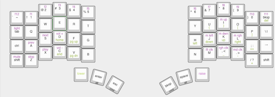
I’m currently proficient on a 56 key layout, and didn’t see a need to go above that. Given that I don’t really use one of my thumb keys, I wanted to explore dropping another one. Losing a key meant that I would need to use Tap-Hold on the thumb keys to have a full set modifiers, or change key map more.
The keymap I’ve settled on is:

During this research I also compiled big lists of all the parts I might need and where to source them. I’ll cover that in a future blog post though.
Design and Learning CAD
With the keymap sorted out, I started to plan the physical design for the keyboard. I started in Inkscape as I know it well. In a handwire build you need a switchplate, and the most common way to fabricate those is via laser cutting. While many laser cutters can use SVG files getting all the measurements precise in Inkscape was really tedious. What I needed was a more precise way to dimension the entire drawing.
What I needed was CAD software. Unfortunately CAD software is often hideously expensive for non-professional use. However, there are open source projects that make free CAD software. Of the options I found FreeCAD resonated the most with me. The documentation for the project is reasonably thorough and there are many video tutorials available. After several failed attempts, I was able to get of my design built in FreeCAD. However, I had a few stumbling points. Getting sketches ‘fully constrained’ can be pretty tedious. FreeCAD doesn’t do much automatically and once you’re overconstrained its recommendations are poor. Later, when you modify a sketch that has been used to create a solid feature it doesn’t always update the model. You then have to manually fiddle with parameters on each feature in the model to propagate updates.
I later discovered OnShape. Onshape is browser-based CAD that has a free tier if your models are public. I found OnShape to be much easier to operate compared to FreeCad. Sketches don’t need to be manually constrained as much, feature update automatically when sketches are changed, and 3D fillets haven’t caused cryptic model errors.

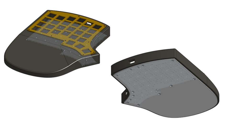
This is where I am currently with the CAD design. I’m planning on getting the switchplate laser cut out of brass, and the case body milled out of walnut as my brother has a small 3-axis CNC machine that I can use. If I didn’t have access to that CNC machine I would be considering 3D printing solutions.
That’s it for this first part. In the next post I’ll cover the electrical research, design, prototyping and firmware proof of concepts.
There are no comments, be the first!